- 您现在的位置:买卖IC网 > Sheet目录1214 > EVAL-ADE7880EBZ (Analog Devices Inc)BOARD EVAL FOR ADE7880
�� �
�
�ADE7880�
�Data� Sheet�
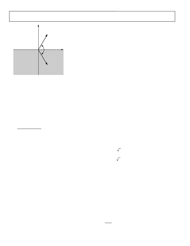
�ACTIVE� (–)�
�REACTIVE� (–)�
�PF� (+)�
�ACTIVE� (+)�
�REACTIVE� (–)�
�PF� (–)�
�CAPACITIVE:�
�CURRENT� LEADS�
�VOLTAGE�
�enabled� on� both� the� active� and� apparent� energies.� This� is� done�
�by� setting� the� xLWATT� and� xLVA� bits� in� the� LCYCMODE�
�register� (Address� 0xE702).� The� update� rate� of� the� power� factor�
�measurement� is� now� an� integral� number� of� half� line� cycles� that�
�can� be� programmed� into� the� LINECYC� register� (Address� 0xE60C).�
�θ� =� +60°�
�θ� =� –60°�
�PF� =� –0.5�
�PF� =� +0.5�
�V�
�For� full� details� on� setting� up� the� line� cycle� accumulation� mode�
�see� the� Line� Cycle� Active� Energy� Accumulation� Mode� and� Line�
��Note� that� the� power� factor� measurement� is� effected� by� the� no�
�ACTIVE� (–)�
�REACTIVE� (+)�
�PF� (–)�
�I�
�ACTIVE� (+)�
�REACTIVE� (+)�
�PF� (+)�
�INDUCTIVE:�
�CURRENT� LAGS�
�VOLTAGE�
��section).� If� the� apparent� energy� no� load� is� true,� then� the� power�
�factor� measurement� is� set� to� 1.� If� the� no� load� condition� based�
�on� total� active� and� apparent� energies� is� true,� the� power� factor�
�Figure� 81.� Capacitive� and� Inductive� Loads�
�As� shown� in� Figure� 81,� the� reactive� power� measurement� is�
�negative� when� the� load� is� capacitive,� and� positive� when� the� load�
�is� inductive.� The� sign� of� the� reactive� power� can� therefore� be�
�used� to� reflect� the� sign� of� the� power� factor.� Note� that� the� ADE7880�
�computes� the� fundamental� reactive� power,� so� its� sign� is� used� as�
�the� sign� of� the� absolute� power� factor.� If� the� fundamental�
�reactive� power� is� in� no� load� state,� then� the� sign� of� the� power�
�factor� is� the� sign� of� the� total� active� power.�
�The� mathematical� definition� of� power� factor� is� shown� in�
�Equation� 47:�
�Power� Factor� =� (Sign� Fundamental� Reactive� Power)� �
�measurement� is� set� at� 0.�
�The� ADE7880� also� computes� the� power� factor� on� the�
�fundamental� and� harmonic� components� based� on� the�
�fundamental� and� harmonic� active,� reactive� and� apparent�
�powers.� See� the� Harmonics� Calculations� section� for� details.�
�HARMONICS� CALCULATIONS�
�The� ADE7880� contains� a� harmonic� engine� that� analyzes� one�
�phase� at� a� time.� Harmonic� information� is� computed� with� a� no�
�attenuation� pass� band� of� 2.8� kHz� (corresponding� to� a� ?3� dB�
�bandwidth� of� 3.3� kHz)� and� it� is� specified� for� line� frequencies�
�between� 45� Hz� and� 66� Hz.� Neutral� current� can� also� be� analyzed�
��Total Active Power�
�Apparent� Power�
�(47)�
�presents� a� synthesized� diagram� of� the� harmonic� engine,� its�
�settings� and� its� output� registers.�
�As� previously� mentioned,� the� ADE7880� provides� a� power� factor�
�measurement� on� all� phases� simultaneously.� These� readings� are�
�provided� into� three� 16-bit� signed� registers,� APF� (Address�
�Theory� of� Operation�
�Consider� an� nonsinusoidal� ac� system� supplied� by� a� voltage,� v(t)�
�that� consumes� the� current� i(t).� Then�
�v� (� t� )� =� ∑� V� k� 2� sin� (� kωt� +� φ� k� )�
�i� (� t� )� =� ∑� I� k� 2� sin� (� k� ω� t� +� γ� k� )�
�0xE609� )� for� Phase� A,� BPF� (Address� 0xE60A)� for� Phase� B,� and�
�CPF� (Address� 0xE60B)� for� Phase� C.� The� registers� are� signed�
�twos� complement� register� with� the� MSB� indicating� the� polarity�
�of� the� power� factor.� Each� LSB� of� the� APF,� BPF,� and� CPF�
�registers� equates� to� a� weight� of� 2� ?15� ,� hence� the� maximum�
�∞�
�k� =� 1�
�∞�
�k� =� 1�
�(48)�
�N� =� ?�
�?� ?�
�register� value� of� 0x7FFF� equating� to� a� power� factor� value� of� 1.�
�The� minimum� register� value� of� 0x8000� corresponds� to� a� power�
�factor� of� ?1.� If� because� of� offset� and� gain� calibrations,� the� power�
�factor� is� outside� the� ?1� to� +1� range,� the� result� is� set� at� ?1� or� +1�
�depending� on� the� sign� of� the� fundamental� reactive� power.�
�By� default� the� instantaneous� total� phase� active� and� apparent�
�powers� are� used� to� calculate� the� power� factor� and� the� registers�
�are� updated� at� a� rate� of� 8� kHz.� The� sign� bit� is� taken� from� the�
�instantaneous� fundamental� phase� reactive� energy� measurement�
�on� each� phase.�
�Should� a� measurement� with� more� averaging� be� required,� the�
�ADE7880� provides� an� option� of� using� the� line� cycle� accumulation�
�measurement� on� the� active� and� apparent� energies� to� determine�
�the� power� factor.� This� option� provides� a� more� stable� power�
�factor� reading.� This� mode� is� enabled� by� setting� the� PFMODE�
�bit� (Bit� 7)� in� the� LCYCMODE� register� (Address� 0xE702).� When�
�where:�
�V� k� ,� I� k� are� rms� voltage� and� current,� respectively,� of� each�
�harmonic.�
�Φ� k� ,� γ� k� are� the� phase� delays� of� each� harmonic.�
�ω� is� the� angular� velocity� at� the� fundamental� (line)� frequency� f.�
�The� ADE7880� harmonics� calculations� are� specified� for� line�
�frequencies� between� 45� Hz� and� 66� Hz.� The� phase� nominal�
�voltage� used� as� time� base� must� have� an� amplitude� greater� than�
�20%� of� full� scale.�
�The� number� of� harmonics� N� that� can� be� analyzed� within� the�
�2.8� kHz� pass� band� is� the� whole� number� of� 2800/f.� The� absolute�
�maximum� number� of� harmonics� accepted� by� the� ADE7880�
�is� 63.�
�?� 2800� ?�
�?� ,� N≤63�
�f�
�this� mode� is� enabled� the� line� cycle� accumulation� mode� must� be�
�Rev.� A� |� Page� 56� of� 104�
�发布紧急采购,3分钟左右您将得到回复。
相关PDF资料
EVAL-ADE7953EBZ
BOARD EVAL FOR ADE7953
EVAL-ADF4002EBZ1
BOARD EVAL FOR ADF4002
EVAL-ADG788EBZ
BOARD EVALUATION FOR ADG788
EVAL-ADM1021AEB
BOARD EVAL FOR ADM1021
EVAL-ADM1023EB
BOARD EVAL FOR ADM1023
EVAL-ADM1031EB
BOARD EVAL FOR ADM1031
EVAL-ADM1062TQEBZ
BOARD EVALUATION FOR ADM1062TQ
EVAL-ADM1075CEBZ
BOARD EVAL FOR ADM1075
相关代理商/技术参数
EVAL-ADE7880EBZ
制造商:Analog Devices 功能描述:ADE7880, ENERGY METER, 3 PH, SPI, I2C, E
EVAL-ADE7913EBZ
制造商:AD 制造商全称:Analog Devices 功能描述:3-Channel, Isolated, Sigma-Delta ADC with SPI
EVAL-ADE7953EBZ
功能描述:BOARD EVAL FOR ADE7953 RoHS:是 类别:编程器,开发系统 >> 评估演示板和套件 系列:- 标准包装:1 系列:PSoC® 主要目的:电源管理,热管理 嵌入式:- 已用 IC / 零件:- 主要属性:- 次要属性:- 已供物品:板,CD,电源
EVAL-ADF4001EBZ2
制造商:Analog Devices 功能描述:Evaluation Board For Pll Frequency Synthesizer 制造商:Analog Devices 功能描述:ADF4001 PLL SYNTHESIZER EVAL BOARD
EVAL-ADF4002EB1
制造商:Analog Devices 功能描述:EVAL BOARD - Bulk
EVAL-ADF4002EBZ1
功能描述:BOARD EVAL FOR ADF4002 RoHS:是 类别:编程器,开发系统 >> 评估演示板和套件 系列:- 产品培训模块:Obsolescence Mitigation Program 标准包装:1 系列:- 主要目的:电源管理,电池充电器 嵌入式:否 已用 IC / 零件:MAX8903A 主要属性:1 芯锂离子电池 次要属性:状态 LED 已供物品:板
EVAL-ADF4007EBZ1
功能描述:BOARD EVALUATION FOR ADF4007EB1 RoHS:是 类别:编程器,开发系统 >> 评估演示板和套件 系列:- 标准包装:1 系列:PSoC® 主要目的:电源管理,热管理 嵌入式:- 已用 IC / 零件:- 主要属性:- 次要属性:- 已供物品:板,CD,电源
EVAL-ADF4106EB1
制造商:Analog Devices 功能描述:PLL, Frequency Synthesizer